
Learn how to control LED brightness using a potentiometer and Arduino through PWM (Pulse Width Modulation). Step-by-step guide with circuit diagram, code, and troubleshooting. Ideal for beginners and DIY electronics learners.
Introduction
🔍 What is a 10K Ohm 3-Pin 15mm Shaft Potentiometer?
A 10K Ohm 3-Pin 15mm Shaft Potentiometer is a rotary variable resistor commonly used for adjusting levels such as voltage, current, or signal intensity in electronic circuits. It is especially popular in Arduino-based projects to provide analog input control, such as adjusting LED brightness, motor speed, or sensor thresholds.
📦 Technical Specifications:
| Feature | Description |
|---|---|
| Resistance | 10K Ohm (10,000 Ohms) |
| Number of Pins | 3 (Terminal 1: VCC, Terminal 2: Output wiper, Terminal 3: GND) |
| Shaft Type | Round, usually 6mm diameter with 15mm length for easy knob attachment |
| Rotation Angle | Typically 270° (some may go up to 300°) |
| Power Rating | ~0.1 to 0.5W (depends on model) |
| Mount Type | Through-hole (suitable for breadboards and PCBs) |
⚙️ How It Works:
A potentiometer has three terminals:
- Terminal 1 → Connects to 5V
- Terminal 3 → Connects to GND
- Terminal 2 (Wiper) → Provides a variable voltage output based on the rotation of the shaft
By rotating the shaft, the internal resistive track varies the voltage at the wiper pin, which can then be read by a microcontroller’s analog pin (e.g., A0 on Arduino).
🧠 Common Use Cases:
- LED brightness control
- Audio volume knobs
- LCD contrast adjustment
- Motor speed regulation
- User input in menu-driven interfaces
💡 Why 10K Ohm?
10K is a standard value that offers a good balance between sensitivity and current draw. It is ideal for interfacing with microcontrollers, as it doesn’t draw excessive current while still being highly responsive to user input.
What the Project Does
In this hands-on Arduino project, you will learn how to control the brightness of an LED using a potentiometer and the PWM (Pulse Width Modulation) technique. This project is perfect for understanding analog input and output handling in embedded systems.
Real-World Use Cases
- Dimmable lighting systems
- Fan speed controllers
- Audio volume controls
- Analog user input interfaces for automation
Skill Level
Beginner-Friendly (Ideal for Arduino newcomers)
Expected Outcome
- Understand PWM and analogRead/analogWrite functions
- Learn to read analog sensor values using a potentiometer
- Practice mapping values between two ranges
- Build a basic user interface using simple components
Components Required
| Quantity | Component | Description | Buy Link |
|---|---|---|---|
| 1 | Arduino UNO | Micro controller Board | Buy on Elecsynergy |
| 1 | LED | Standard 5mm LED (any color) | Buy on Elecsynergy |
| 1 | Potentiometer (10K) | Variable resistor to control voltage | Buy on Elecsynergy |
| 1 | Resistor (220Ω) | For limiting current to LED | Buy on Elecsynergy |
| 1 | Breadboard | For building the circuit | Buy on Elecsynergy |
| 5 | Jumper Wires | Male-to-male connectors | Buy on Elecsynergy |
| 1 | USB Cable for Arduino | For powering and uploading code | Buy on Elecsynergy |
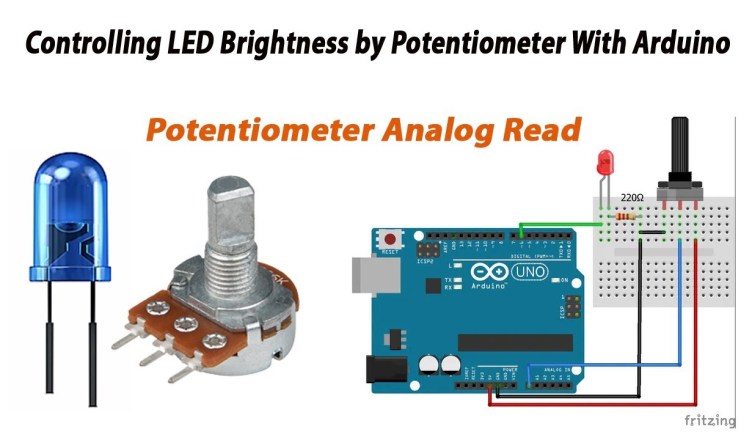
Circuit Diagram + Explanation
LED:
- Anode (+) → Arduino Pin 9 (PWM)
- Cathode (–) → GND via 220Ω resistor
Potentiometer:
- One terminal → 5V
- Other terminal → GND
- Middle pin → A0 (Analog Input)
Circuit Explanation:
- The potentiometer acts as a voltage divider.
- Arduino reads the analog value from the middle pin (A0).
- It then maps this value to a PWM signal to control the LED brightness.

Arduino Code – Commented
// LED Brightness Control using Potentiometer (PWM)

const int potPin = A0;  // Potentiometer connected to A0
const int ledPin = 9;   // LED connected to PWM pin 9
int potValue = 0;       // Variable to store the analog value
int ledValue = 0;       // Variable to store the PWM value

void setup() {
  pinMode(ledPin, OUTPUT);     // Set LED pin as output
  Serial.begin(9600);          // Initialize Serial Monitor for debugging
}

void loop() {
  potValue = analogRead(potPin);          // Read the potentiometer value (0–1023)
  ledValue = map(potValue, 0, 1023, 0, 255); // Map it to 0–255 for PWM
  analogWrite(ledPin, ledValue);          // Set the brightness using PWM

  // Optional Debugging
  Serial.print("Potentiometer Value: ");
  Serial.print(potValue);
  Serial.print(" → LED PWM Value: ");
  Serial.println(ledValue);

  delay(10); // Small delay for stability
}
Working Explanation
- Potentiometer Input: Acts as a variable voltage source from 0V to 5V.
- Arduino Analog Read: Reads the voltage and returns a value from 0 to 1023.
- PWM Output: Converts that into a value from 0 to 255 and sends it to pin 9 using PWM.
- LED Brightness: Varies in intensity as the potentiometer is rotated.
PWM lets the Arduino output simulate analog voltage by quickly toggling HIGH and LOW signals. This technique is widely used to control power delivered to devices.
Demo / Output Preview
Turn the potentiometer knob and watch the LED brightness increase or decrease smoothly.
This replicates real-world dimming systems like smart lighting.
Troubleshooting & Tips
- LED not lighting up?
- Check resistor value and polarity of LED
- Make sure LED is on a PWM-enabled pin (e.g., 3, 5, 6, 9, 10, 11)
- No variation in brightness?
- Confirm that the potentiometer middle leg is connected to A0
- Check wiring to 5V and GND
- Serial Monitor not showing values?
- Ensure baud rate is set to 9600
- Use correct COM port
Project Expansion Ideas
- Control Multiple LEDs: Add RGB LEDs and control individual colors with 3 potentiometers.
- PWM Fan Speed Controller: Replace LED with a small DC fan.
- OLED Display: Show analog and PWM values in real-time.
- Button-based Brightness Levels: Replace potentiometer with tactile buttons.
- Remote Controlled Dimming: Add IR receiver or Bluetooth module.
Conclusion
You’ve successfully built a LED brightness controller using Arduino and a potentiometer. This is an essential foundation for understanding user input, analog interfacing, and PWM output.
🔁 What You’ve Learned:
- Reading analog values with
analogRead() - Outputting PWM signals using
analogWrite() - Mapping one range of data to another using
map() - Basic UI design with potentiometers
🛒 Buy the Complete Kit
Get all components in a single kit:
👉 Buy Now from Elecsynergy


